TikZ and PGF Manual
The Basic Layer
104 Using Paths
104.1 Overview
Once a path has been constructed, it can be used in different ways. For example, you can draw the path or fill it or use it for clipping.
Numerous graph parameters influence how a path will be rendered. For example, when you draw a path, the line width is important as well as the dashing pattern. The options that govern how paths are rendered can all be set with commands starting with \pgfset. All options that influence how a path is rendered always influence the complete path. Thus, it is not possible to draw part of a path using, say, a red color and drawing another part using a green color. To achieve such an effect, you must use two paths.
In detail, paths can be used in the following ways:
-
1. You can stroke (also known as draw) a path.
-
2. You can add arrow tips to a path.
-
3. You can fill a path with a uniform color.
-
4. You can clip subsequent renderings against the path.
-
5. You can shade a path.
-
6. You can use the path as bounding box for the whole picture.
You can also perform any combination of the above, though it makes no sense to fill and shade a path at the same time.
To perform (a combination of) the first four actions, you can use the following command:
-
\pgfusepath{⟨actions⟩} 
-
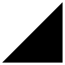
• fill fills the path. See Section 104.4 for further details.

                        \begin{pgfpicture}

                          \pgfpathmoveto{\pgfpointorigin}

                          \pgfpathlineto{\pgfpoint{1cm}{1cm}}

                          \pgfpathlineto{\pgfpoint{1cm}{0cm}}

                          \pgfusepath{fill}

                        \end{pgfpicture}
-
• stroke strokes the path. See Section 104.2 for further details.

                        \begin{pgfpicture}

                          \pgfpathmoveto{\pgfpointorigin}

                          \pgfpathlineto{\pgfpoint{1cm}{1cm}}

                          \pgfpathlineto{\pgfpoint{1cm}{0cm}}

                          \pgfusepath{stroke}

                        \end{pgfpicture}
-
• draw has the same effect as stroke.
-
• clip clips all subsequent drawings against the path. Always suppresses arrow tips. See Section 104.5 for further details.

                        \begin{pgfpicture}

                          \pgfpathmoveto{\pgfpointorigin}

                          \pgfpathlineto{\pgfpoint{1cm}{1cm}}

                          \pgfpathlineto{\pgfpoint{1cm}{0cm}}

                          \pgfusepath{stroke,clip}

                          \pgfpathcircle{\pgfpoint{1cm}{1cm}}{0.5cm}

                          \pgfusepath{fill}

                        \end{pgfpicture}
-
• discard discards the path, that is, it is not used at all. Giving this option (alone) has the same effect as giving an empty options list.
Applies the given ⟨actions⟩ to the current path. Afterwards, the current path is (globally) empty. The following actions are possible:
When more than one of the first three actions are given, they are applied in the above ordering, regardless of their ordering in ⟨actions⟩. Thus, {stroke,fill} and {fill,stroke} have the same effect.
To shade a path, use the \pgfshadepath command, which is explained in Section 114.
104.2 Stroking a Path
When you use \pgfusepath{stroke} to stroke a path, several graphic parameters influence how the path is drawn. The commands for setting these parameters are explained in the following.
Note that all graphic parameters apply to the path as a whole, never only to a part of it.
All graphic parameters are local to the current {pgfscope}, but they persists past TeX groups, except for the interior rule (even-odd or nonzero) and the arrow tip kinds. The latter graphic parameters only persist till the end of the current TeX group, but this may change in the future, so do not count on this.
104.2.1 Graphic Parameter: Line Width
-
\pgfsetlinewidth{⟨line width⟩} 
This command sets the line width for subsequent strokes (in the current pgfscope). The line width is given as a normal TeX dimension like 0.4pt or 1mm.

                    \begin{pgfpicture}

                      \pgfsetlinewidth{1mm}

                      \pgfpathmoveto{\pgfpoint{0mm}{0mm}}

                      \pgfpathlineto{\pgfpoint{2cm}{0mm}}

                      \pgfusepath{stroke}

                      \pgfsetlinewidth{2\pgflinewidth} % double in size

                      \pgfpathmoveto{\pgfpoint{0mm}{5mm}}

                      \pgfpathlineto{\pgfpoint{2cm}{5mm}}

                      \pgfusepath{stroke}

                    \end{pgfpicture}
-
\pgflinewidth 
You can access the current line width via the TeX dimension \pgflinewidth. It will be set to the correct line width, that is, even when a TeX group closed, the value will be correct since it is set globally, but when a {pgfscope} closes, the value is set to the correct value it had before the scope.
104.2.2 Graphic Parameter: Caps and Joins
104.2.3 Graphic Parameter: Dashing
-
\pgfsetdash{⟨list of even length of dimensions⟩}{⟨phase⟩} 
Sets the dashing of a line. The first entry in the list specifies the length of the first solid part of the list. The second entry specifies the length of the following gap. Then comes the length of the second solid part, following by the length of the second gap, and so on. The ⟨phase⟩ specifies where the first solid part starts relative to the beginning of the line.

                    \begin{pgfpicture}

                      \pgfsetdash{{0.5cm}{0.5cm}{0.1cm}{0.2cm}}{0cm}

                      \pgfpathmoveto{\pgfpoint{0mm}{0mm}}

                      \pgfpathlineto{\pgfpoint{2cm}{0mm}}

                      \pgfusepath{stroke}

                      \pgfsetdash{{0.5cm}{0.5cm}{0.1cm}{0.2cm}}{0.1cm}

                      \pgfpathmoveto{\pgfpoint{0mm}{1mm}}

                      \pgfpathlineto{\pgfpoint{2cm}{1mm}}

                      \pgfusepath{stroke}

                      \pgfsetdash{{0.5cm}{0.5cm}{0.1cm}{0.2cm}}{0.2cm}

                      \pgfpathmoveto{\pgfpoint{0mm}{2mm}}

                      \pgfpathlineto{\pgfpoint{2cm}{2mm}}

                      \pgfusepath{stroke}

                    \end{pgfpicture}
Use \pgfsetdash{}{0pt} to get a solid dashing.
104.2.4 Graphic Parameter: Stroke Color
-
\pgfsetstrokecolor{⟨color⟩} 
Sets the color used for stroking lines to ⟨color⟩, where ⟨color⟩ is a LaTeX color like red or black!20!red. Unlike the \color command, the effect of this command lasts till the end of the current {pgfscope} and not till the end of the current TeX group.
The color used for stroking may be different from the color used for filling. However, a \color command will always “immediately override” any special settings for the stroke and fill colors.
In plain TeX, this command will also work, but the problem of defining a color arises. After all, plain TeX does not provide LaTeX colors. For this reason, pgf implements a minimalistic “emulation” of the \definecolor, \colorlet, and \color commands. Only gray-scale and rgb colors are supported. For most cases this turns out to be enough.

                    \begin{pgfpicture}

                      \pgfsetlinewidth{1pt}

                      \color{red}

                      \pgfpathcircle{\pgfpoint{0cm}{0cm}}{3mm} \pgfusepath{fill,stroke}

                      \pgfsetstrokecolor{black}

                      \pgfpathcircle{\pgfpoint{1cm}{0cm}}{3mm} \pgfusepath{fill,stroke}

                      \color{red}

                      \pgfpathcircle{\pgfpoint{2cm}{0cm}}{3mm} \pgfusepath{fill,stroke}

                    \end{pgfpicture}
-
\pgfsetcolor{⟨color⟩} 
Sets both the stroke and fill color. The difference to the normal \color command is that the effect lasts till the end of the current {pgfscope}, not only till the end of the current TeX group.
104.2.5 Graphic Parameter: Stroke Opacity
You can set the stroke opacity using \pgfsetstrokeopacity. This command is described in Section 115.
104.2.6 Inner Lines
When a path is stroked, it is possible to request that it is stroked twice, the second time with a different line width and a different color. This is a useful effect for creating “double” lines, for instance by setting the line width to 2pt and stroking a black line and then setting the inner line width to 1pt and stroking a white line on the same path as the original path. This results in what looks like two lines, each of thickness 0.5pt, spaced 1pt apart.
You may wonder why there is direct support for this “double stroking” in the basic layer. After all, this effect is easy to achieve “by hand”. The main reason is that arrow tips must be treated in a special manner when such “double lines” are present. First, the order of actions is important: First, the (thick) main line should be stroked, then the (thin) inner line, and only then should the arrow tip be drawn. Second, the way an arrow tip looks typically depends strongly on the width of the inner line, so the arrow tip code, which is part of the basic layer, needs access to the inner line thickness.
Two commands are used to set the inner line width and color.
-
\pgfsetinnerlinewidth{⟨dimension⟩} 
This command sets the width of the inner line. Whenever a path is stroked (and only then), it will be stroked normally and, afterward, it is stroked once more with the color set to the inner line color and the line width set to ⟨dimension⟩.
In case arrow tips are added to a path, the path is first stroked normally, then the inner line is stroked, and then the arrow tip is added. In case the main path is shortened because of the added arrow tip, this shortened path is double stroked, not the original path (which is exactly what you want).
When the inner line width is set to 0pt, which is the default, no inner line is stroked at all (not even a line of width 0pt). So, in order to “switch off” double stroking, set ⟨dimension⟩ to 0pt.
The setting of the inner line width is local to the current TeX group and not to the current pgf scope.
Note that inner lines will not be drawn for paths that are also used for clipping. However, this may change in the future, so you should not depend on this.

                    \begin{pgfpicture}

                      \pgfpathmoveto{\pgfpointorigin}

                      \pgfpathlineto{\pgfpoint{1cm}{1cm}}

                      \pgfpathlineto{\pgfpoint{1cm}{0cm}}

                      \pgfsetlinewidth{2pt}

                      \pgfsetinnerlinewidth{1pt}

                      \pgfusepath{stroke}

                    \end{pgfpicture}
-
\pgfsetinnerstrokecolor{⟨color⟩} 
This command sets the ⟨color⟩ that is to be used when the inner line is stroked. The effect of this command is also local to the current TeX group.

                    \begin{pgfpicture}

                      \pgfpathmoveto{\pgfpointorigin}

                      \pgfpathlineto{\pgfpoint{1cm}{1cm}}

                      \pgfpathlineto{\pgfpoint{1cm}{0cm}}

                      \pgfsetlinewidth{2pt}

                      \pgfsetinnerlinewidth{1pt}

                      \pgfsetinnerstrokecolor{red!50}

                      \pgfusepath{stroke}

                    \end{pgfpicture}
104.3 Arrow Tips on a Path
After a path has been drawn, pgf can add arrow tips at the ends, depending on how the tips key is set, on whether stroke or clip are used and on whether the path contains closed subpaths. The exact rules when arrow tips are added are explained in Section 16.2.
-
\pgfsetarrowsstart{⟨start arrow tip specification⟩} 
Sets the arrow tip kind used at the start of a (possibly curved) path. The syntax of the ⟨start arrow specification⟩ is detailed in Section 16.4.
To “clear” the start arrow, say \pgfsetarrowsstart{}.

                    \usepgflibrary {arrows.meta}

                    \begin{pgfpicture}

                      \pgfsetarrowsstart{Latex[length=10pt]}

                      \pgfpathmoveto{\pgfpointorigin}

                      \pgfpathlineto{\pgfpoint{1cm}{0cm}}

                      \pgfusepath{stroke}

                      \pgfsetarrowsstart{Computer
                    Modern
                    Rightarrow}

                      \pgfpathmoveto{\pgfpoint{0cm}{2mm}}

                      \pgfpathlineto{\pgfpoint{1cm}{2mm}}

                      \pgfusepath{stroke}

                    \end{pgfpicture}
The effect of this command persists only till the end of the current TeX scope.
-
\pgfsetarrowsend{⟨end arrow tip specification⟩} 
Sets the arrow tip kind used at the end of a path.

                    \usepgflibrary {arrows.meta}

                    \begin{pgfpicture}

                      \pgfsetarrowsstart{Latex[length=10pt]}

                      \pgfsetarrowsend{Computer
                    Modern
                    Rightarrow}

                      \pgfpathmoveto{\pgfpointorigin}

                      \pgfpathlineto{\pgfpoint{1cm}{0cm}}

                      \pgfusepath{stroke}

                    \end{pgfpicture}
-
\pgfsetarrows{⟨argument⟩} 
The ⟨argument⟩ can be of the form ⟨start arrow tip specification⟩-⟨end arrow tip specification⟩. In this case, both the start and the end arrow specification are set:

                    \usepgflibrary {arrows.meta}

                    \begin{pgfpicture}

                      \pgfsetarrows{Latex[length=10pt]->>}

                      \pgfpathmoveto{\pgfpointorigin}

                      \pgfpathlineto{\pgfpoint{1cm}{0cm}}

                      \pgfusepath{stroke}

                    \end{pgfpicture}
Alternatively, ⟨argument⟩ can be of the form [⟨arrow keys⟩]. In this case, the ⟨arrow keys⟩ will be set for all arrow tips in the current scope, see Section 16.4.5.
-
\pgfsetshortenstart{⟨dimension⟩} 
This command will shortened the start of every stroked path by the given dimension. This shortening is done in addition to automatic shortening done by a start arrow, but it can be used even if no start arrow is given.
It is usually better to use the sep key with arrow tips.
This command is useful if you wish arrows or lines to “stop shortly before” a given point.

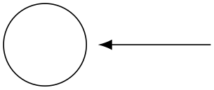
                    \usepgflibrary {arrows.meta}

                    \begin{pgfpicture}

                      \pgfpathcircle{\pgfpointorigin}{5mm}

                      \pgfusepath{stroke}

                      \pgfsetarrows{Latex-}

                      \pgfsetshortenstart{4pt}

                      \pgfpathmoveto{\pgfpoint{5mm}{0cm}} % would be on the circle

                      \pgfpathlineto{\pgfpoint{2cm}{0cm}}

                      \pgfusepath{stroke}

                    \end{pgfpicture}
-
\pgfsetshortenend{⟨dimension⟩} 
Works like \pgfsetshortenstart.
104.4 Filling a Path
Filling a path means coloring every interior point of the path with the current fill color. It is not always obvious whether a point is “inside” a path when the path is self-intersecting and/or consists or multiple parts. In this case either the nonzero winding number rule or the even-odd crossing number rule is used to decide which points lie “inside”. These rules are explained in Section 15.5.
104.4.1 Graphic Parameter: Interior Rule
You can set which rule is used using the following commands:
-
\pgfseteorule 
Dictates that the even-odd rule is used in subsequent fillings in the current TeX scope. Thus, for once, the effect of this command does not persist past the current TeX scope.

                    \begin{pgfpicture}

                      \pgfseteorule

                      \pgfpathcircle{\pgfpoint{0mm}{0cm}}{7mm}

                      \pgfpathcircle{\pgfpoint{5mm}{0cm}}{7mm}

                      \pgfusepath{fill}

                    \end{pgfpicture}
-
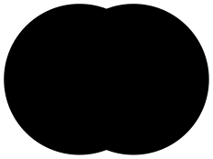
\pgfsetnonzerorule 
Dictates that the nonzero winding number rule is used in subsequent fillings in the current TeX scope. This is the default.

                    \begin{pgfpicture}

                      \pgfsetnonzerorule

                      \pgfpathcircle{\pgfpoint{0mm}{0cm}}{7mm}

                      \pgfpathcircle{\pgfpoint{5mm}{0cm}}{7mm}

                      \pgfusepath{fill}

                    \end{pgfpicture}
104.4.2 Graphic Parameter: Filling Color
-
\pgfsetfillcolor{⟨color⟩} 
Sets the color used for filling paths to ⟨color⟩. Like the stroke color, the effect lasts only till the next use of \color.
104.4.3 Graphic Parameter: Fill Opacity
You can set the fill opacity using \pgfsetfillopacity. This command is described in Section 115.
104.5 Clipping a Path
When you add the clip option, the current path is used for clipping subsequent drawings. The same rule as for filling is used to decide whether a point is inside or outside the path, that is, either the even-odd rule or the nonzero rule.
Clipping never enlarges the clipping area. Thus, when you clip against a certain path and then clip again against another path, you clip against the intersection of both.
The only way to enlarge the clipping path is to end the {pgfscope} in which the clipping was done. At the end of a {pgfscope} the clipping path that was in force at the beginning of the scope is reinstalled.
104.6 Using a Path as a Bounding Box
When you add the use as bounding box option, the bounding box of the picture will be enlarged such that the path in encompassed, but any subsequent paths of the current TeX scope will not have any effect on the size of the bounding box. Typically, you use this command at the very beginning of a {pgfpicture} environment. Alternatively, you can use \pgfresetboundingbox, followed by \pgfusepath{use as bounding box} to overrule the picture’s bounding box completely.
Left right.
                Left

                \begin{pgfpicture}

                  \pgfpathrectangle{\pgfpointorigin}{\pgfpoint{2ex}{1ex}}

                  \pgfusepath{use
                as
                bounding
                box} % draws nothing


                  \pgfpathcircle{\pgfpointorigin}{2ex}

                  \pgfusepath{stroke}

                \end{pgfpicture}

                right.