TikZ and PGF Manual
Libraries
59 Matrix Library
-
TikZ Library matrix
\usetikzlibrary{matrix} %
LaTeX
and plain
TeX
\usetikzlibrary[matrix] % ConTeXt
This library package defines additional styles and options for creating matrices. The basic matrix styles and options can be
found in Section 20.
59.1 Matrices of Nodes
A matrix of nodes is a TikZ matrix in which each cell contains a node. In this case it is bothersome having to write \node{ at the beginning of each cell and }; at the end of each cell. The following key simplifies typesetting such matrices.
-
/tikz/matrix of nodes(no value) 
-
1. You can modify, say, the row 2 column 3 style to pass special options to this particular cell.
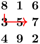
\usetikzlibrary {matrix}
\begin{tikzpicture}[row 2 column 3/.style=red]
\matrix [matrix of nodes]
{
8 & 1 & 6 \\
3 & 5 & 7 \\
4 & 9 & 2 \\
};
\end{tikzpicture}
-
2. At the beginning of a cell, you can use a special syntax. If a cell starts with a vertical bar, then everything between this bar and the next bar is passed on to the node command.
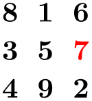
\usetikzlibrary {matrix}
\begin{tikzpicture}
\matrix [matrix of nodes]
{
8 & 1 & 6 \\
3 & 5 & |[red]| 7 \\
4 & 9 & 2 \\
};
\end{tikzpicture}
You can also use an option like |[red] (seven)| to give a different name to the node.
Note that the & character also takes an optional argument, which is an extra column skip.

\usetikzlibrary {matrix}
\begin{tikzpicture}
\matrix [matrix of nodes]
{
8 &[1cm] 1 &[3mm] |[red]| 6 \\
3 & 5 & |[red]| 7 \\
4 & 9 & 2 \\
};
\end{tikzpicture}
-
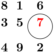
3. If your cell starts with a \path command or any command that expands to \path, which includes \draw, \node, \fill and others, the \node{ startup code and the }; code are suppressed. This means that for this particular cell you can provide totally different contents.
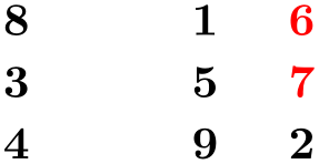
\usetikzlibrary {matrix}
\begin{tikzpicture}
\matrix [matrix of nodes]
{
8 & 1 & 6 \\
3 & 5 & \node[red]{7}; \draw(0,0) circle(10pt);\\
4 & 9 & 2 \\
};
\end{tikzpicture}
Conceptually, this key adds \node{ at the beginning and }; at the end of each cell and sets the anchor of the node to base. Furthermore, it adds the option name option to each node, where the name is set to ⟨matrix name⟩-⟨row number⟩-⟨column number⟩. For example, if the matrix has the name my matrix, then the node in the upper left cell will get the name my matrix-1-1.
                    \usetikzlibrary {matrix}

                    \begin{tikzpicture}

                      \matrix (magic) [matrix of nodes]

                      {

                        8
                    & 1
                    & 6
                    \\

                        3
                    & 5
                    & 7
                    \\

                        4
                    & 9
                    & 2
                    \\

                      };


                      \draw[thick,red,->] (magic-1-1) |-
                    (magic-2-3);

                    \end{tikzpicture}
You may wish to add options to certain nodes in the matrix. This can be achieved in three ways.
-
/tikz/matrix of math nodes(no value) 
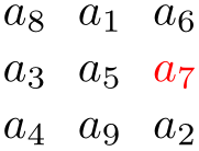
This style is almost the same as the previous style, only $ is added at the beginning and at the end of each node, so math mode will be switched on in all nodes.
                    \usetikzlibrary {matrix}

                    \begin{tikzpicture}

                      \matrix [matrix of math nodes]

                      {

                        a_8
                    & a_1
                    &
                            a_6
                    \\

                        a_3
                    & a_5
                    &
                    |[red]|
                    a_7 \\

                        a_4
                    & a_9
                    &
                            a_2
                    \\

                      };

                    \end{tikzpicture}
-
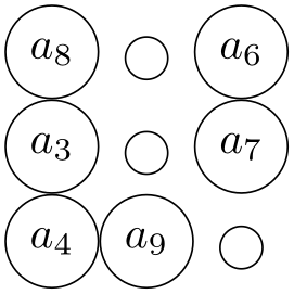
/tikz/nodes in empty cells=⟨true or false⟩ (default true) 
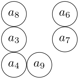
When set to true, a node (with empty contents) is put in empty cells. Normally, empty cells are just, well, empty. The style can be used together with both a matrix of nodes and a matrix of math nodes.
                    \usetikzlibrary {matrix}

                    \begin{tikzpicture}

                      \matrix [matrix of math nodes,nodes={circle,draw}]

                      {

                        a_8
                    &     &
                    a_6 \\

                        a_3
                    &     &
                    a_7 \\

                        a_4
                    & a_9
                    &     \\

                      };

                    \end{tikzpicture}
                    \usetikzlibrary {matrix}

                    \begin{tikzpicture}

                      \matrix [matrix of math nodes,nodes={circle,draw},nodes in empty cells]

                      {

                        a_8
                    &     &
                    a_6 \\

                        a_3
                    &     &
                    a_7 \\

                        a_4
                    & a_9
                    &     \\

                      };

                    \end{tikzpicture}
59.2 End-of-Lines and End-of-Row Characters in Matrices of Nodes
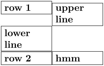
Special care must be taken about the usage of the \\ command inside a matrix of nodes. The reason is that this character is overloaded in TeX: On the one hand, it is used to denote the end of a line in normal text; on the other hand it is used to denote the end of a row in a matrix. Now, if a matrix contains node which in turn may have multiple lines, it is unclear which meaning of \\ should be used.
This problem arises only when you use the text width option of nodes. Suppose you write a line like
                \matrix [text width=5cm,matrix of nodes]

                {

                  first
                row &
                upper line
                \\ lower
                line \\

                  second
                row &
                hmm \\

                };
This leaves TeX trying to riddle out how many rows this matrix should have. Do you want two rows with the upper right cell containing a two-line text. Or did you mean a three row matrix with the second row having only one cell?
Since TeX is not clairvoyant, the following rules are used:
-
1. Inside a matrix, the \\ command, by default, signals the end of the row, not the end of a line in a cell.
-
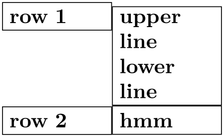
2. However, there is an exception to this rule: If a cell starts with a TeX-group (this is, with {), then inside this first group the \\ command retains the meaning of “end of line” character. Note that this special rule works only for the first group in a cell and this group must be at the beginning.
The net effect of these rules is the following: Normally, \\ is an end-of-row indicator; if you want to use it as an end-of-line indicator in a cell, just put the whole cell in curly braces. The following example illustrates the difference:
                \usetikzlibrary {matrix}

                \begin{tikzpicture}

                  \matrix [matrix of nodes,nodes={text width=16mm,draw}]

                  {

                    row
                1 &
                upper line
                \\ lower
                line \\

                    row
                2 &
                hmm \\

                  };

                \end{tikzpicture}
                \usetikzlibrary {matrix}

                \begin{tikzpicture}

                  \matrix [matrix of nodes,nodes={text width=16mm,draw}]

                  {

                    row
                1 & {upper
                line \\ lower
                line} \\

                    row
                2 &
                hmm \\

                  };

                \end{tikzpicture}
Note that this system is not fool-proof. If you write things like a&b{c\\d}\\ in a matrix of nodes, an error will result (because the second cell did not start with a brace, so \\ retained its normal meaning and, thus, the second cell contained the text b{c, which is not balanced with respect to the number of braces).
59.3 Delimiters
Delimiters are parentheses or braces to the left and right of a formula or a matrix. The matrix library offers options for adding such delimiters to a matrix. However, delimiters can actually be added to any node that has the standard anchors north, south, north west and so on. In particular, you can add delimiters to any rectangle box. They are implemented by “measuring the height” of the node and then adding a delimiter of the correct size to the left or right using some after node magic.
-
/tikz/left delimiter=⟨delimiter⟩(no default) 
-
/tikz/every delimiter(style, initially empty) 
-
/tikz/every left delimiter(style, initially empty) 
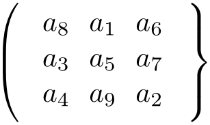
This option can be given to a any node that has the standard anchors north, south and so on. The ⟨delimiter⟩ can be any delimiter that is acceptable to TeX’s \left command.
                    \usetikzlibrary {matrix}

                    \begin{tikzpicture}

                      \matrix [matrix of math nodes,left delimiter=(,right delimiter=\}]

                        {

                          a_8 & a_1 & a_6 \\

                          a_3 & a_5 & a_7 \\

                          a_4 & a_9 & a_2 \\

                        };

                      \end{tikzpicture}
                    \usetikzlibrary {matrix}

                    \begin{tikzpicture}

                      \node [fill=red!20,left delimiter=(,right delimiter=\}]

                          {$\displaystyle\int_0^1 x\,dx$};


                    \end{tikzpicture}
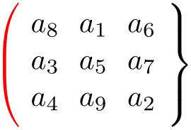
This style is executed for every delimiter. You can use it to shift or color delimiters or do whatever.
This style is additionally executed for every left delimiter.

                        \usetikzlibrary {matrix}

                        \begin{tikzpicture}

                          [every left delimiter/.style={red,xshift=1ex},

                           every right delimiter/.style={xshift=-1ex}]

                          \matrix [matrix of math nodes,left delimiter=(,right delimiter=\}]

                            {

                              a_8 & a_1 & a_6 \\

                              a_3 & a_5 & a_7 \\

                              a_4 & a_9 & a_2 \\

                            };

                          \end{tikzpicture}
-
/tikz/above delimiter=⟨delimiter⟩(no default) 
-
/tikz/every above delimiter(style, initially empty) 
This option allows you to add a delimiter above the node. It is implemented by rotating a left delimiter.
                    \usetikzlibrary {matrix}

                    \begin{tikzpicture}

                      \matrix [matrix of math nodes,%

                               left delimiter=\|,right delimiter=\rmoustache,%

                               above delimiter=(,below delimiter=\}]

                        {

                          a_8 & a_1 & a_6 \\

                          a_3 & a_5 & a_7 \\

                          a_4 & a_9 & a_2 \\

                        };

                      \end{tikzpicture}
Works as above.