Manual for Package pgfplots
2D/3D Plots in LATeX, Version 1.18.2
https://github.com/pgf-tikz/pgfplots
The Reference
4.21Symbolic Coordinates and User Transformations
pgfplots supports user transformations which can be applied to input and output coordinates. Suppose the plot shall display days versus account statements over time. Then, one wants to visualize date versus credit balance. But: dates need to be transformed to numbers before doing so! Furthermore, tick labels shall be displayed as dates as well. This, and more general transformations, can be implemented using the x coord trafo and y coord trafo keys.
This section applies to users who want to have non-standard input coordinates. If you have normal numbers which don’t need to be transformed and you like to have special symbols as tick labels, you should consider using the xticklabels (yticklabels) key described on page (??).
See also Section 4.23.1 for different types of transformations and their interaction.
-
• any input coordinates (specified with \addplot or axis cs),
-
• any user-specified extra x ticks and extra y ticks options,
These code keys allow arbitrary coordinate transformations which are applied to input coordinates and output tick labels.
The x coord trafo and y coord trafo command keys take one argument which is the input coordinate. They are expected to set \pgfmathresult to the final value.
At this level, the input coordinate is provided as it is found in the
\addplot statement. For example, if \(x\)-coordinates are
actually of the form
 year
year -
- month
month -
- day
day , for example 2008-01-05, then a useful coordinate transformation would transform this string into a number (see
below for a predefined realization).
In short, no numerics has been applied to input coordinates when this transformation is applied.68
The input coordinate transformation is applied to
The output coordinate transformation x coord inv trafo is applied to tick positions just before evaluating the xticklabel and yticklabel keys. The argument to x coord inv trafo is a fixed point number (which may have trailing zeros after the period). The tick label code may use additional macros defined by the inverse transformation.
Remark: pgfplots will continue to produce tick positions as usual, no extra magic is applied. It may be necessary to provide tick positions explicitly if the default doesn’t respect the coordinate space properly.
The initial value of these keys is
which simply disables the transformation (the same for \(y\), of course).
It might be necessary to set
in order to avoid number formatting routines on \tick or numerics for tick scale methods. This is done automatically by the predefined symbolic coordinate styles (see below).
4.21.1String Symbols as Input Coordinates
It is possible to provide a string dictionary to pgfplots. An input coordinate can then use any symbol provided in that dictionary.
-
/pgfplots/symbolic x coords={
 dictionary
 }
}
-
/pgfplots/symbolic y coords={
 dictionary
 }
}
-
/pgfplots/symbolic z coords={
 dictionary
 }
}
A style which sets
x coord trafo and
x coord inv trafo (or the
respective y or
z variants) such that any element in
 dictionary
 is a valid input coordinate. The
 dictionary
 can be a comma separated list or a list terminated with ‘\\’. In both cases, white space is
considered to be part of the names (use ‘%’ at end of lines).
The dictionary will assign integer numbers to every element (starting with \(0\)). These integers are used internally for arithmetics. Finally, the inverse transformation takes a fixed point number and maps it to the nearest integer, and that integer is mapped into the dictionary.
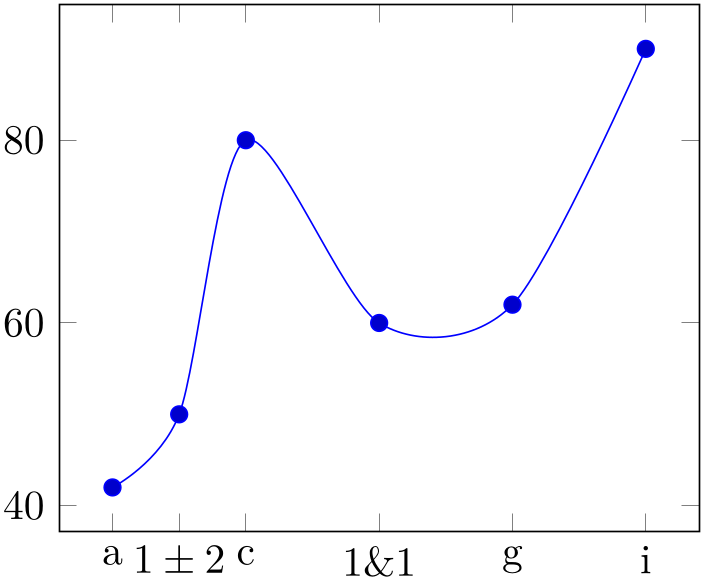
% Preamble: \pgfplotsset{width=7cm,compat=1.18}
\begin{tikzpicture}
\begin{axis}[
symbolic x coords={a,b,c,d,e,f,g,h,i},
]
\addplot+ [smooth] coordinates {
(a,42)
(b,50)
(c,80)
(f,60)
(g,62)
(i,90)
};
\end{axis}
\end{tikzpicture}
The effect of the transformation is simply that input coordinates can be elements of the dictionary and tick labels will be chosen out of this dictionary as well.
Note that symbolic x coords is more or less equivalent to explicitly provided xtick positions and xticklabels:
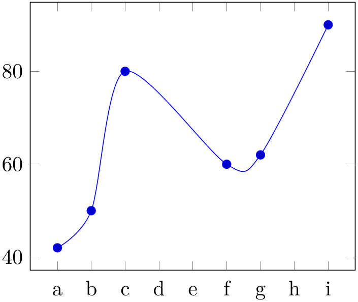
% Preamble: \pgfplotsset{width=7cm,compat=1.18}
\begin{tikzpicture}
\begin{axis}[
xtick={0,1,2,...,20},
xticklabels={a,b,c,d,e,f,g,h,i},
xticklabel style={
anchor=base,
yshift=-\baselineskip,
},
]
\addplot+ [smooth] coordinates {
(0,42)
(1,50)
(2,80)
(5,60)
(6,62)
(8,90)
};
\end{axis}
\end{tikzpicture}
The difference is that the approach with symbolic x coords is simpler to read whereas the xtick approach is simpler with respect to coordinate arithmetics (for example to increase limits using enlargelimits). The xticklabel style here is an attempt to align all tick labels at their base line (which would be useful for symbolic x coords as well as soon as labels have characters which exceed the baseline).
The key symbolic x coords and its variants accepts a comma-separated list of strings. These can be arbitrary and can even contain unexpandable material:69
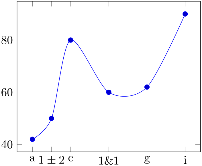
% Preamble: \pgfplotsset{width=7cm,compat=1.18}
\begin{tikzpicture}
\begin{axis}[
symbolic x coords={a,$1 \pm 2$,c,d,1\&1,f,g,h,i},
xtick=data,
]
\addplot+ [smooth] coordinates {
(a,42)
($1 \pm 2$,50)
(c,80)
(1\&1,60)
(g,62)
(i,90)
};
\end{axis}
\end{tikzpicture}
In any case, the arguments of
 dictionary
 must be met precisely, including any white spaces.
Symbolic coords are useful since they reduce the burden to map strings to indices and vice versa. However, they have a caveat: what if you want to set xmin to something to the left of the first symbolic x coord? This is impossible since any input coordinate is expected to be contained in symbolic x coord. To allow such modifications nevertheless, pgfplots checks for the magic prefix [normalized]:
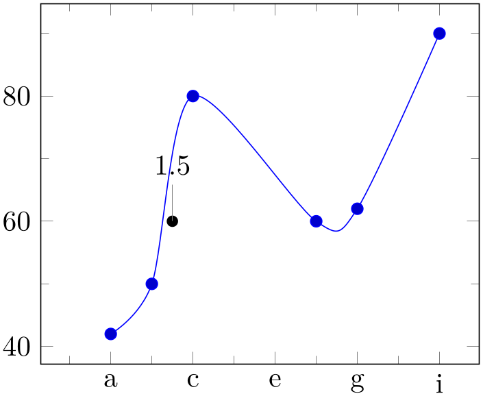
% Preamble: \pgfplotsset{width=7cm,compat=1.18}
\begin{tikzpicture}
\begin{axis}[
symbolic x coords={a,b,c,d,e,f,g,h,i},
xmin={[normalized]-1.7},
minor tick num=1,
]
\addplot+ [smooth] coordinates {
(a,42)
(b,50)
(c,80)
(f,60)
(g,62)
(i,90)};
\fill (axis cs:{[normalized]1.5},60)
circle (2pt) coordinate [pin={$1.5$}];
\end{axis}
\end{tikzpicture}
Whenever pgfplots finds a symbolic coordinate which starts with the precise string ‘[normalized]’, it will interpret everything after the prefix to be a normalized number and no symbol. In our example, xmin will be set to \(-1.7\), i.e. something to the left of \(a\) (which would be \(0\) according to the definition above). Furthermore, the custom \node is placed at \((1.5,60)\) despite the fact the \(1.5\) is no defined symbol – but we know that it is between b and c which are dictionary entry \(1\) and \(2\), respectively.
the option to add tick and/or grid lines at every encountered coordinate using xtick=data (or minor xtick=data).
4.21.2Dates as Input Coordinates
The already mentioned application of using dates as input coordinates has been predefined, together with support for hours and minutes. It relies on the pgf calendar library which converts dates to numbers in the Julian calendar. Then, one coordinate unit is one day.
-
/pgfplots/date coordinates in=
 coordinate
-
• \Hour expands to the hour component (but omits leading zeros),
-
• \Minute expands to the minute component (omits leadings zeros),
-
• \lowlevel expands to the low level number representing the tick,
Installs
x coord trafo and
x coord inv trafo (or the
respective variant for
 coordinate
 ) such that ISO dates of the form
 year
year -
- month
month -
- day
day are accepted. Here,
 coordinate
 is usually one of x, y, or z, but it can also contain stuff like hist/data.
After installing this style, input values like 2006-02-28 will be converted to an “appropriate” integer using the Julian calendar. Input coordinates may be of the form
 year
year -
- month
month -
- day
day
or they may contain times as
 year
year -
- month
month -
- day
day
 hour
hour :
: minute
 .
.
The result of the transformation are numbers where one unit is one day and times are fractional numbers.
The transformation is implemented using the pgf-calendar module, see [7, Calendar Library]. This reference also contains more information about extended syntax options for dates.
The inverse transformation provides the following macros which are available during tick label evaluation (i.e. when used inside of xticklabel or yticklabel):
This allows to use \day.\month.\year or \day. \hour:\minute inside of xticklabel, for example.
A complete example (with fictional data) is shown below.
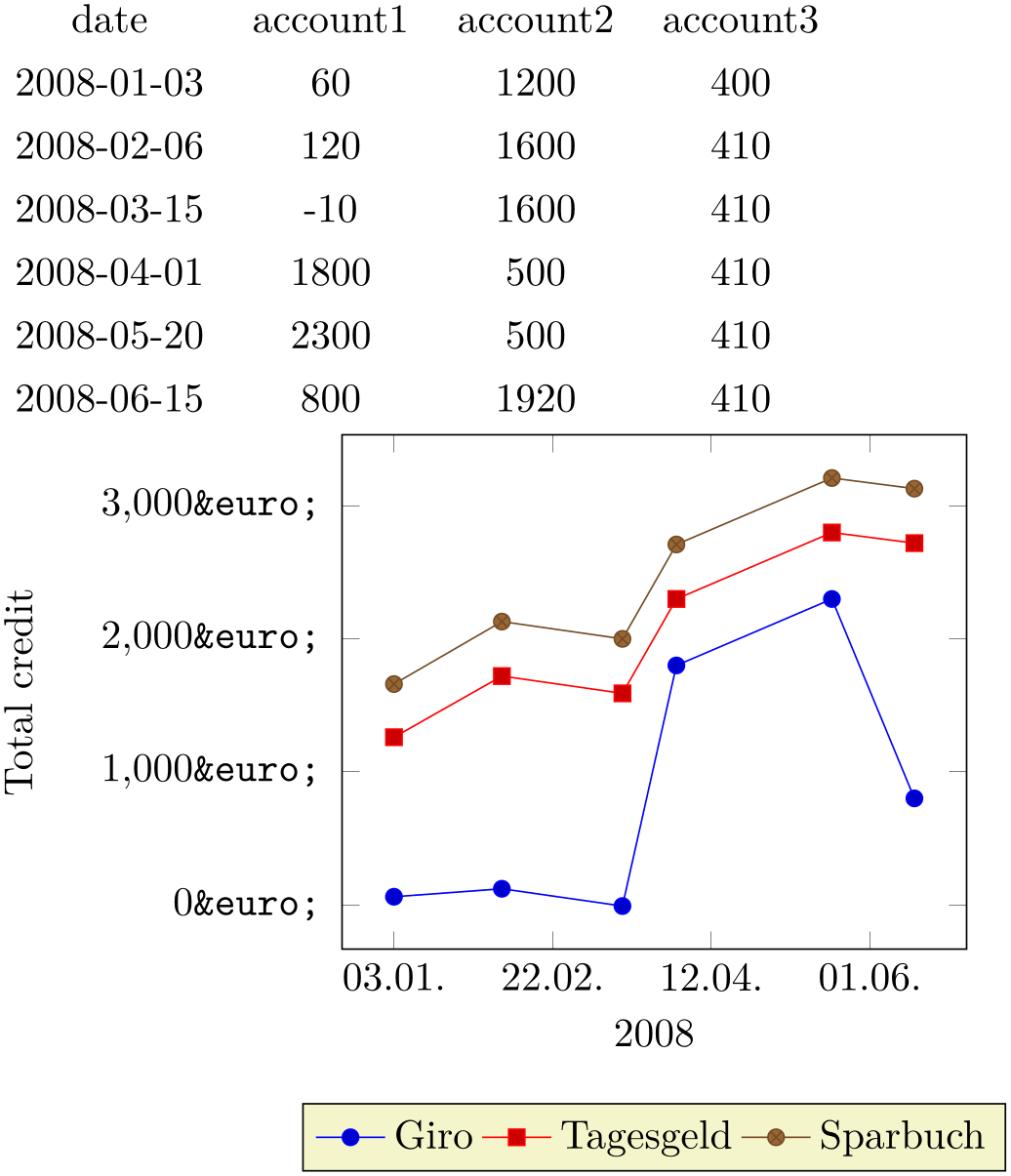
% Preamble: \pgfplotsset{width=7cm,compat=1.18}\usepgfplotslibrary{dateplot}
% requires \usepgfplotslibrary{dateplot} !
\pgfplotstabletypeset[string type]{plotdata/accounts.dat}
\begin{tikzpicture}
\begin{axis}[
date coordinates in=x,
xticklabel={\day.\month.},
xlabel={2008},
stack plots=y,
yticklabel={\pgfmathprintnumber{\tick}\EUR{}}, % <- requires \usepackage{eurosym}
ylabel=Total credit,
ylabel style={yshift=10pt},
legend style={
at={(0.5,-0.3)},anchor=north,legend columns=-1,
},
]
\addplot table [x=date,y=account1] {plotdata/accounts.dat};
\addplot table [x=date,y=account2] {plotdata/accounts.dat};
\addplot table [x=date,y=account3] {plotdata/accounts.dat};
\legend{Giro,Tagesgeld,Sparbuch}
\end{axis}
\end{tikzpicture}
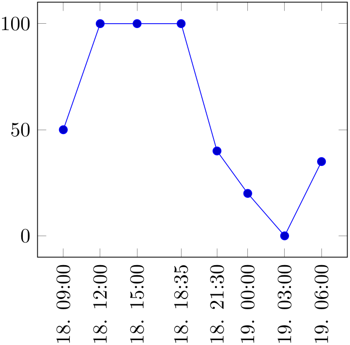
% Preamble: \pgfplotsset{width=7cm,compat=1.18}\usepgfplotslibrary{dateplot}
% requires \usepgfplotslibrary{dateplot} !
\begin{tikzpicture}
\begin{axis}[
date coordinates in=x,
xtick=data,
xticklabel style=
{rotate=90,anchor=near xticklabel},
xticklabel=\day. \hour:\minute,
]
                        \addplot coordinates
                    {
(2009-08-18 09:00, 050)
(2009-08-18 12:00, 100)
(2009-08-18 15:00, 100)
(2009-08-18 18:35, 100)
(2009-08-18 21:30, 040)
(2009-08-19, 020)
(2009-08-19 3:00, 000)
(2009-08-19 6:0, 035)
};
\end{axis}
\end{tikzpicture}
-
/pgfplots/date ZERO=
 year
year -
- month
month -
- day
day 
A technical key which defines the \(0\) coordinate of date coordinates in.
pgfplots up to and including version 1.12 required this value. As of version 1.13, the first encountered coordinate is used as date ZERO, i.e. it is assigned automatically without user intervention.
Users will never see the resulting numbers, so one probably never needs to change this value. This key allows to set the result as needed.

